For many makers, a project idea sometime may take a very long time to materialised. This project for creating a STM32G070-based PalpTop handheld took me almost a year, starting from the initial idea, to making the final PCB, and still not 100% completed yet.
The PCB for this project is sponsored by PCBway. PCBWay is a China-based PCB Fabrication house, it offers services ranging from PCB Fabrication, PCB Assembly as well as CNC and high quality 3D printing. This is my first time using PCB fabrication service from PCBWay, for more details about the sponsorship and my first impression about the service, please see “Making PCB and PCBWay” for more details.
PalmTop - An STM32G070 Development Board with a Keyboard
It all started from finding a suitable MCU for my daily projects in the middle of component shortage. More than a year ago when global semiconductor industry is in short supply, my STM32F103 blue pill was destroyed due to accidentally connection to a wrong power rail, it is not the first one that has been destroyed, and I was reluctant to buy another one although it is dirt cheap on Aliexpress. First, there are too many fake STM32F103 on Aliexpress, even sometime the picture on the website shown a seemly genuise STM32F103, you could end up getting a fake part marked as xxx32F103, secondly, those blue pill board has know design failure and if not handled carefully, it could easily be destroyed like what happened to my blue pill. Third, there are places where I could get the genuise part and build my own more reliable blue pill, but in the middle of global shortage, some of those parts (if available) was priced at redicilousely high. While searching for available MCUs that I could buy, I noticed there are plenty of supply for STM32G070 series and costs less than $2 on LCSC. The G070 series is an entry-level Cortex M1+ chip with new manufacturing process compare to decade-old STM32F1 series, and therefore the silicon is smaller in nm measurement and lower nm silicon translates to higher density and less power consumption than the older chips.
ST microelectronics already has a Nucleo board based on STM32G070RB (64-pin package) selling at very reasonable price, but I don’t think that I will need 64-pin package for any of my projects, plus the Nucleo board was out of stock at the time I was searching for the MCU a year ago, so I want to have a 48-pin package (G70CB) or even 32-pin package (G70KB) chip as those are the chips that I'm likely to be used for my production project once I completed a development using my development board. But at the same time, I don't want to just make a development board that simply breakout every pins, I want to have something that could demonstrate the usage of the chip and at the same time can be used as a development board.
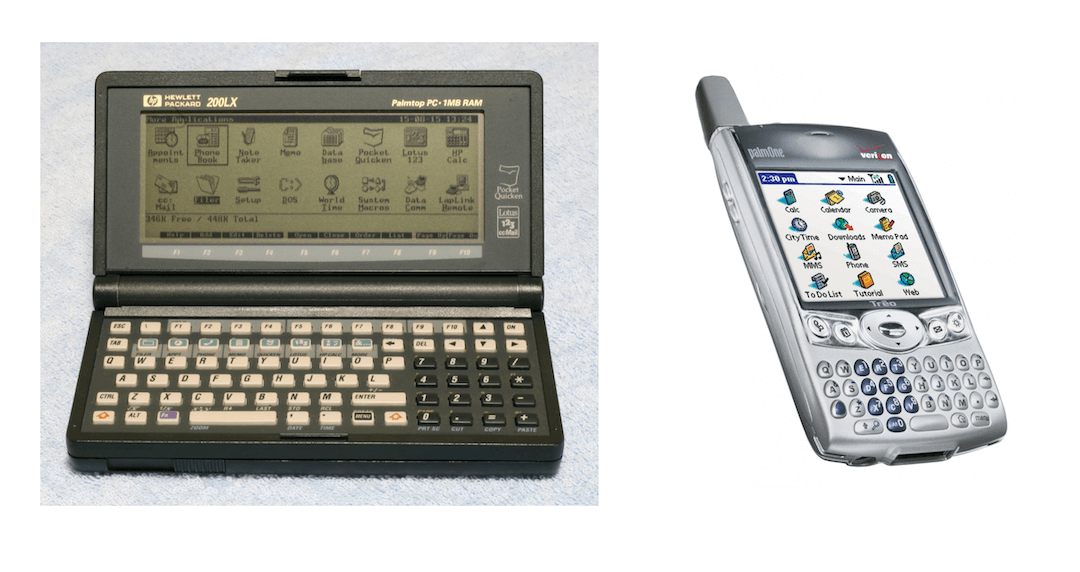
In the early 90, I had an HP 200LX handheld computer, it has build-in Lotus123, PocketQuicken, HP Calc and running DOS system. Among all the features, it has a very easy to type keyboard. I had it with me till when I joint Palm Computing as it’s Asia Sales Director for Wireless Business Unit almost 10 year later, the Treo650 from Palm again has a surprisingly usable keyboard and I kept using various generations of Treo until a couple of years after Apple iPhone 4 was released.
So instead of making a simply STM32G070 development board (eventually I will probably make one), I have an idea of building a PalmTop handheld with full keyboard and running either a BASIC interpreter or LISP interpreter (or both) for rapid prototyping.
Finding a display - UC1609 192x64 LCD module
Although OLED display modules are very common and cheap nowadays, but most of it only supports up to 128 pixels wide, which means it can only display 128/6 = 21 characters per line (with 6x8-pixel font), I prefer to have something wider, it would make a BASIC statement like 10 for i=1 to 100 step 5 more readable across a line. Another reason is that oled consumed more battery than an LCD. Eventually I found the 192x64 LCD display module which uses an LCD controller UC1609 from Ultrachip, Taiwan. This LCD module will be able to display 32 characters x 8 lines on a single screen. There are a couple of Arduino libraries available on GitHub that I probably could use but I want to get familiar with the chip, so the first thing I did is to write an Arduino library for the display.
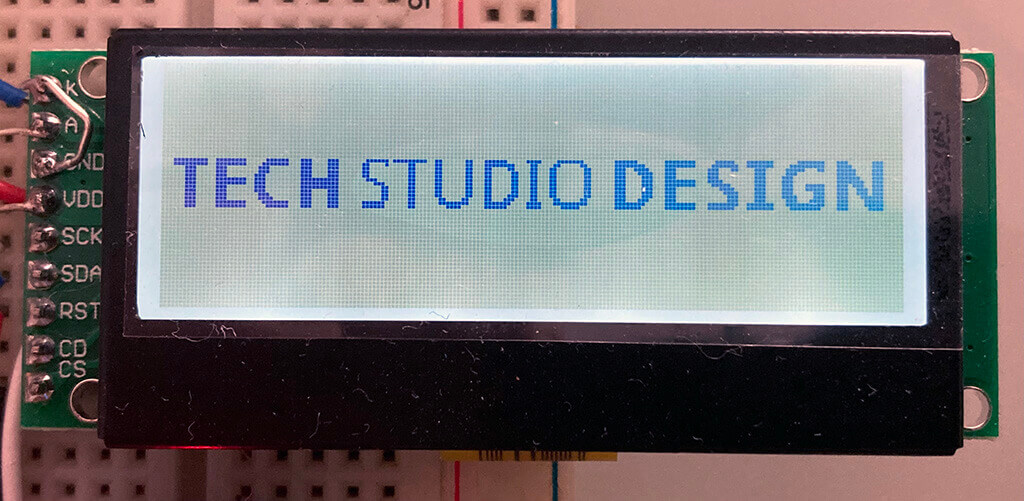
The UC1609 itself is operated at 3.3v, the LCD module have two versions with operating voltage of 5V or 3.3V. The 5V version comes with an LDO chip soldered on the back of the display module, which bring the 5V input down to 3.3v before feeding into the module. The 3.3V version comes without the LDO chip and allows direct supply of 3.3V to the module. I bought the 3.3V version. The Backlight should always be connected to 3.3V according to datasheet.
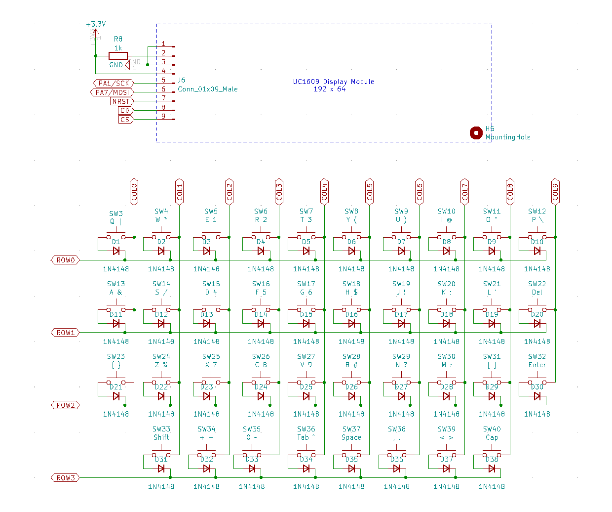
The display uses SPI interface and capable to operated at 8MHz clock speed so I set the library to operate at the speed while allows user to set different clock speed by defining a macro #define SPI_CLOCK 4000000UL. Other than the standard 4-line SPI interface, it also required an additional GPIO line for C/D (command/data) signalling. Together with backlight cathode/anode and VCC/GND, it has a 9-pin header at the left side of the display module.
The display module comes with a 9-pin header on the left, other than the pins for the SPI communication and power, there are two pins (A - for Anode, K - for Cathode) for the backlight LED, I connected 3.3v to the Anode via a 1k resistor and tie the Cathode to the ground.
To create an LCD driver (or in Arduino world, it often called a library), it is a matter of reading the datasheet (often over and over again) to figure out how to control every aspect of the device and write small function for each feature. As I've done several LCD display drivers before and had talked about how to read datasheet and create an LCD driver before at "How to create Arduino library from Arduino sketch" and "How to use LCD 5110 (PCD 8544) with Arduino" so I won't describes the code in detail here. The UC1609 Arduino library is open-source, documentation as well as example codes are available at my GitHub UC1609.
Design a full-feature keyboard
Once the display module work, it is time to work on keyboard. It is difficult to test a keyboard matrix on a breadboard so I use one of those 4x4 kaypad for a partial development.
The 4x4 Keypad is not exactly a full-feature keyboard, but it functions the same as an ultimate full feature keyboard, the difference is that the ultimate full feature keyboard would have 4x10 matrix instead of 4x4. Although I only had a 4x4 Keypad, I wrote a test code based on a full-feature keyboard with 4x10 matrix, and test part of the keyboard by connecting the 4 column pins of the 4x4 keypad to the 4 of the eventually 10 pins to simulate a section of the full-feature keyboard. Once everything work based on the test, I design the keyboard schematic which consists of 4 rows and 10 columns keyboard matrix.
One thing unique about the Palm Treo650 keyboard is that it doesn't really follow the traditional key arrangement for numeric and symbol keys, all the numeric and symbols are carefully re-arranged for telephony application and thumb-typing.
Since what I want is eventually I could write code in BASIC or LISP on the device, so in order to meet software programming need, the keyboard will need to support more symbols that the Treo can supported. All the key definitions can be defined via software with two arrays, so I defined my keyboard based on the Treo keyboard, but add more symbols and changed some of the key assignments. Since all the numeric and symbol requires press the Shift key first, to make it easilier for typing a number (e.g. 12345678), once the Shift key is pressed, it "lock" in the numeric/symbol mode until the second press of Shift key to shift back to alphanumeric mode. Press the CapLock key, however only print the subssequent chacater as uppder character and it will automatically shift out of the CapLock mode.
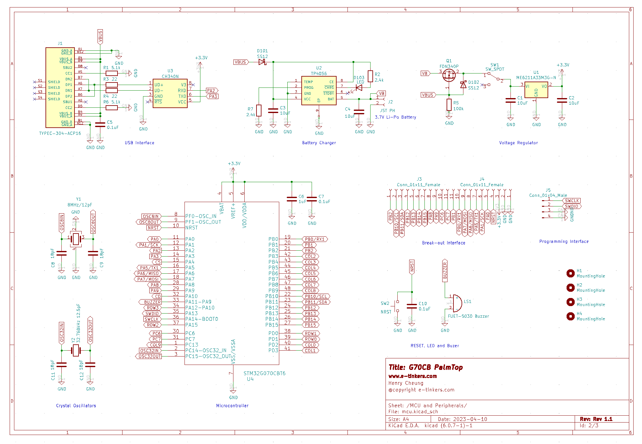
The MCU and Charging Circuit
After confirming that the keyboard and display module work, I started the overall schematic design. I envision that the PalmTop handheld will be powered by a Li-ion rechargeable battery (I happened to have many 2900mAh 104060 (10mm x 40mm x 60mm) battery) with me, so it make sense to have an on-board battery charger. For charging IC, I choose TP4056 as it cheap and readily available compare to the Microchip IC that I used before. The Q1 P-Channel MOSFET acts as a load switch to allow the battery to be charged via USB while powring the board. For the same reason I use CH340N over SiliconLab's chip as the USB to UART interface chip as it is available at LCSC.com.
I pick the 48-pin STM32G070KB as the MCU, the keyboard matrix uses a total of 14 GPIO pins for 4 rows x 10 cols, the display module requires two dedicated GPIO pins for Chip Select (CS) and Command/Data (C/D) in addition to the 4-pin SPI interface, and I added a buzzer for the power-up beeping as well as key-pressed beep. There is no LED for the circuit design as the Display module already provided the visual clue for system status. The rest of the 18 GPIO pins are break-out to a 22-pin header, and can be configure as SPI, I2C, UART or GPIO. The MCU is dirven by an external 8MHz crystal and together with internal PLL and clock tree configuration, set the MCU to run at maximum speed of 64MHz. There is also a 32.768kHz crystal for powering the internal RTC.
Making PCB and PCBWay
The board design was completed at the end of 2022 but I got other daily works that I don't have much time to create the PCB so the project get put on hold for a while. I received an email from PCBWay in mid-Feb 2023, asking whether I'm interested for a partnership program with PCBWay. The arrangement is like this, for any project that I plan to write an article to share on my web site, I can apply to PCBWay for a sponsorhip fee for the proejct, at the same time, I can describe my order experiences with PCBWay on both my website as well as on PCBWay's website. This sounds like a great partnership, so I started to create the PCB and send for fabrication.
Although I'm aware of PCBWay, I'm so far only used JLBPCB services for the past several years, so this is my first experience of using PCBWay's service. PCBWay's website offers more options that professional PCB designers are looking for on special/more advanced materials and treatment (such as Rogers, HDI with buried/blind vias, thermal conductivity, et.c) when comparing with JLCPCB, the quality is slightly better than the JLCPCB on solder paste and drilling alighment when closely examed under a magnified scope. PCBWay's pricing is comparable with JLBPCB but price is higher when the size of the PCB is greater than 10x10cm but is still reasonable and competitvie.
Another thing that is unique about PCBWay is that it offers many kind of "reward" coupons, for example, when I signed up the service, I get a coupon of 5.00 in my inbox, that is sufficient for odering 5 pieces of PCB not larger than 10x10cm. You are not only get this one-time coupon, you could get coupons for filling up your profile, or anwering questionnaire, or recommending friends, or open-sourced your gerber files for others to order your design. All those seems to trying to builds a long-term relationship with you as a customer and encourage you to stay with the service. With the 5.00 coupon that I got, I know my next project will probably with PCBWay.
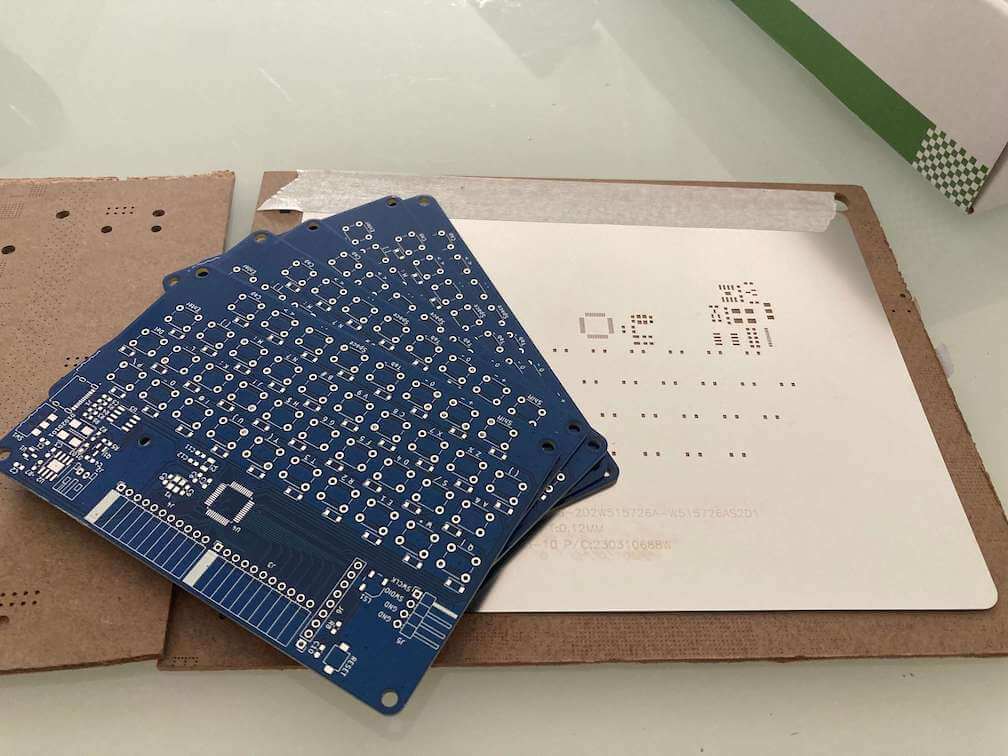
PCBWay charges 10.00 for stencil for size of an approximately A4 paper, as 48-pin STM32G070KB would be difficult to manually apply solder paste without a stencil, so I order the stencil as well.
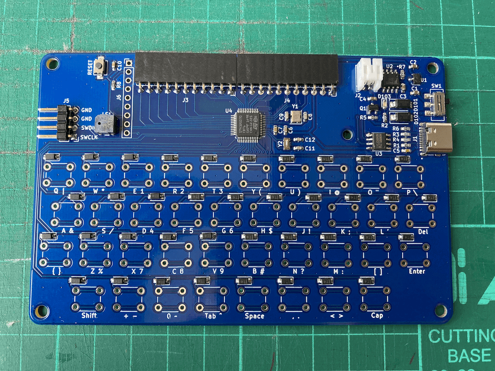
Both the stencil and PCB quality turn out to be very good on the PCBWay part. However I made two mistakes on my part. One mistake is that I accidentially connect the CH340 3.3V output to the 3.3V LDO output, I had to replaced the damaged LDO with a new one and cut out the CH340 3.3V pin. I had since modified the schematic and PCB artwork to correct this mistake. Another mistake is that there is no "=" symbol defined and therefore it was not on the keyboard silkscreen, luckily key function is software-defined, I re-designated the "tab" button to "=", but the silkscreen would have to wait for next PCB revision to correct it.
The size of the PCB of my design is 117mm x 76.5mm, but my home-made reflow hotplate has a heating platform of only 100mm x100mm, so during the reflow I had to do twice to make sure all the components are properly soldered. The result turn out to be quite good.
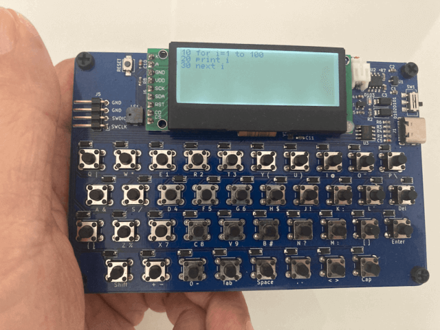
Mostly part of the PCB is covered by the LCD module and the keys. I decided to put the MCU, the crystal circuits and header pins under the LCD module, the back of the UC1609 LCD module also has some components toward the left side of the module, so I make sure that these compoments will not sitting on top of, or come in conact with, the MCU and cyrstals. Once all the surface-mounted components are soldering on the PCB and the board is tested, I then solder the LCD module on top, and result is the picture shown as the feature image at the beginning of this article.
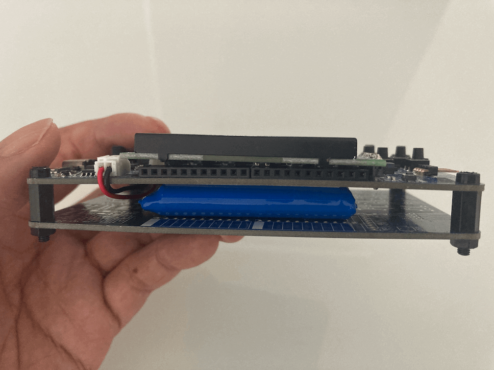
One of the questions during the design stage is how to mount the battery, since the minimum quantity for PCB order is 5 pieces, so I decided to use one of the spare PCBs as the back plate and put the battery in between the actual soldered PCB and the back plate PCB, and secured with 10mm PCB standoffs.
Create Arduino STM32 Core Board Variant for STM32G070 Series
When I bought my first STM32G070CB (32-pin package) and STM32G070KB (48-pin package) chips from LCSC at the beginning of 2022, those chips are so new that I noticed that the Arduino STM32 Core (a.k.a. STM32Duino) does not support the STM32G070 series yet, so I decided to create the board variants for the STM32G070 series and submitted a pull-request to add the support for the STM32G070 series on STM32 Arduino framework, the pull request is quickly accepted and passed all the tests, and get roll into the Arduino STM32 Core v2.3 which was by June 2022.
Although I created a generic MCU support for STM32G070 series for STM32 Arduino Core. The generic STM32G070 support is a bare minimum configuration, allows anyone to use the STM32 Arduino Core with the internal HSI (High Speed Internal clock) and internal LSI(Low Speed Internal clock) with a set of pre-defined generic GPIO pin configuration. My PalmTop however has an external 8MHz crystal as HSE (High Speed External) Clock as well as a 32.768kHz crystal for the LSE (Low Speed External) clock. The pin assignments for many GPIO pins are also different in my design. So if I want to use the STM32 Arduino Core, I need to create a PalmTop specific board variant and make it available on the Arduino IDE.
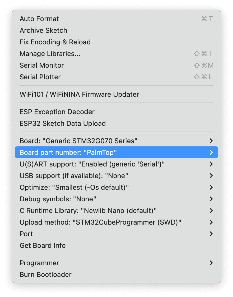
STM32 Arduino Core has a wiki on how to create a new board variant. I had gone through the process once when I create the generic STM32G070 series board variants when I was doing the pull request. But this time I need to created a board variant for PalmTop and install it locally. In order to be able to select the PalmTop as the board from the Arduino IDE, in order to add the custom board variant to Arduino IDE, quit the Arduino IDE, create a hardware directory under where all the Arduino sketches were kept on the PC and add the board variant package there, or follow these steps to clone it from my github.
    $ mkdir -p $HOME/Arduino/hardware
    $ cd $HOME/Arduino/hardware
$ git clone https://github.com/e-tinkers/stm32_board_variants.git variants- Launch Arduino IDE, and select the board from Tools -> Boards -> STM32G070xx Custom Boards -> PalmTop.
Hardware Test Code
The display module was tested on another custom-made STM32G070 board as well as on other MCUs so I know it is working. The keyboard code was partially tested but never on a full-featured 40-key configurtation before. The keyboard code is restructured as a C++ Class almost like an Arduino Library, but the code is tightly depend on the Palmtop hardware configuration, it is not as portable or reusable without modifying the pin assignments and configuration for using it in other project like an Arduino Library.
Test code is available on github together with schematic and PCB files
The Keyboard::begin() initializes all column I/O pins to INPUT_PULLUP and all the row I/O pins to INPUT mode.
The keyboard scanning uses negative logic to allow the circuit to function without external pull-up or pull-down resistors. So, instead of outputing a HIGH on each row when scanning the matrix, each of the row pins is re-config to OUTPUT mode and set it to LOW during each scan, as each column pins is pull-up by the internal pull-up configuration, so it should be HIGH unless a key is pressed which connect the row pin to the column pin, causing the reading of column pin to have a state of LOW instead of HIGH, the column number and row number would be used to retrieve the ASCII value from the matrix array to detect which key is actually pressed.
If ther is no button been pressed, the row pin will be configured back to INPUT (i.e. high impedence), and the next row will be set to OUTPUT and so on.
Kbd.cpp
#include "kbd.h"

void Keyboard::begin() {
    for (int c=0; c<COLS; c++) {
        pinMode(colPins[c], INPUT_PULLUP);
    }

    for (int r=0; r<ROWS; r++) {
        pinMode(rowPins[r], INPUT);
    }
}

char Keyboard::available() {

  static unsigned long startTime = millis();

  if (millis() - startTime > DEBOUNCED_INTERVAL) {
    for (int r=0; r<ROWS; r++) {

      pinMode(rowPins[r], OUTPUT);
      digitalWrite(rowPins[r], LOW);

      for (int c=0; c<COLS; c++) {
        if (digitalRead(colPins[c]) == 0) {
          _keyCode = keys[r][c];

          switch (_keyCode) {
            case SI:    // key shift pressed
              _keyState = !_keyState;
              _keyCode = 0;
              break;
            case SO:    // caplock pressed
              _keyState = CAPLOCK;
              _keyCode = 0;
              break;
            default:
              if (_keyState == SHIFTED) {
                _keyCode = keysShifted[r][c];
              }
              else if (_keyState == CAPLOCK) {
                if (_keyCode >='a' && _keyCode<='z') {
                  _keyCode = keys[r][c] - 0x20;  // capital character
                  _keyState = NORMAL;
                }
                else {
                  _keyState = NORMAL;
                }
              }
              break;
          }
          tone(BUZZER, 4000, 50);
          pinMode(rowPins[r], INPUT);
          startTime = millis();
          return _keyCode;
        }
      }
      pinMode(rowPins[r], INPUT);
      startTime = millis();
    }
  }
  return 0;
}

char Keyboard::read() {
  return _keyCode;
}
The entire testing program is quite simple as its main purpose is to test if all the key hardware components work as per design. I add an SMD buzzer that I never used before to the schematic design, so the test code help to confirm if the buzzer work. The buzzer is used during the power up (a longer beep of 500ms), and whenever a key is pressed (a 50ms short beep).
/*
 *  PalmTop - A STM32G070-based Development Board with keyboard, display and a BASIC interpreter
 *
 *  The pin definitions using in this code is the hardware design of PalmTop board. It requires
 *  a custom board configuration based on stm32duino Arduino_Core_STM32 for PalmTop.
*/

#include <UC1609.h>
#include "image.h"
#include "kbd.h"

// UC1609 display settings
#define CD       PA10
#define CS       PA4
#define RST      -1    // share with MCU's NRST pin

#define CONTRAST 0x38

UC1609 lcd(CS, CD, RST);
Keyboard keyboard;

void startUpScreen() {
  lcd.drawImage(0, 0, 192, 64, logo);
  tone(BUZZER, 4000, 500);
  delay(2000);
  lcd.clearDisplay();
}

void setup() {

  pinMode(BUZZER, OUTPUT);

  keyboard.begin();

  delay(3);     // for LCD to get ready after powering up
  lcd.begin(CONTRAST);
  lcd.setFont(font5x7_extended);

  startUpScreen();

}

void loop() {

  if (keyboard.available()) {
    char c = keyboard.read();
    lcd.write(c);
  }

  delay(1);

}
Next Step - Write an BASIC Interpreter
This project took longer than I expected, if it is not because of PCBWay's email, I would probably procrastinating without getting the PCB done. Another reason that it took longer than I expected partly because it involved several subsystems, from creating LCD driver, to hardware schematic design, to create Arduino Board Variant, to PCB fabrication, assembly and testing. Each subsystem has to be developed and test separately before it could integrated together to create the final product.
As you can see the test code is really not doing much other than can typing and displaying text on the PalmTop. Next step is to write an BASIC interpreter for the Palmtop so that I can carrying the PalmTop with me anywhere I go and write programs in BASIC.
This project looks great. I had something similar to make in mind with RP2040.